
|
|
|
|
|
Tools needed.
Soldering Iron |
Difficulty Rating. o1
*********************
10 |
Time it takes. Roughly 30 minutes to perform the mods and an hour to an hour and a half to replace the components, depending on how good your soldering is.
|
|
How to rebuild " Bullet proof " Atari's Audio Regulator pcb (AR II) including the Sense Mods. Atari's
arcade cabinets came with either an AR
I or an AR II Audio
regulator pcb in them, which not only supplied amplification for the
sounds of the games but also regulated the voltages needed for the
game pcbs to run. The regulator pcbs had +
and -
sensing circuits, which would sense and adjust
the voltages being supplied to the game pcb, over time the components
on this pcb deteriorate with age and can cause critical problems,
by actually upping the voltage supplied to the game pcb so high that
it kills components on the game pcb. |
|
! All notes here are for reference only, i will not be held responsible for any mistakes / damage done to your pcb's ! |
 |
 |
|
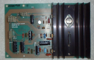
Identifying Audio regulator pcbs. The
picture on the left is an
AR I,
which is the type of Audio regulator pcb you would find in
Asteroids, Lunar
Lander etc.. it is only half the
size of an AR
II pictured on the right,
which you would find in Star Wars,
Pole Position,
Crystal Castles and
many many others |
![]()
 |
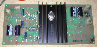
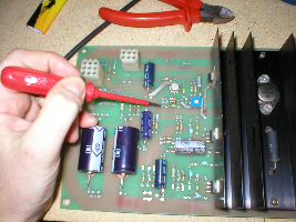
Where
to Start. This is the AR II out of my Atari Star Wars and it has donated itself as a suitable candidate for rebuilding and even though it is working, it hasnt had the sense mods done yet and i have no idea how old the components are on it, so its time it had a bit of refreshing. I'm going to start by performing the sense mods first and then finish off with component replacement. As i have said before AR II's come in different populations and so some have more or less components on them than others, but they will all have the same basic components i am going to replace and will also all have the same sensing circuits that need to be modified. |
![]()
|
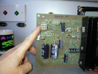
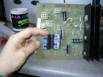
Sense Mods.
With
the pcb facing me upright so i could read the Atari
Audio II wording correctly and not upside down, i located
connector J7 near
the top left hand corner. |
 |
![]()
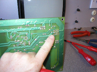 |
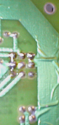
Connector J7 Solder Side.
The modification needs to be performed to the solder side of the pcb, turning the pcb round i looked for the 9 solder blobs near to top right hand corner of the pcb. It is here that i am going to add some small jumpers across some of the solder pads.
|
![]()
|
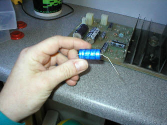
Jumper Wires.
To make some neat jumpers you can use alot of different things, i tend to get an unused resistor or capacitor and cut its legs off, thus giving me some stiff but still flexible wire that is easy to grip and manipulate. I could of used regular wire, but as its stranded it can tend to get a bit fiddly when cut into very small lengths, plus you then have to remove its sheathing.
|
 |
![]()
 |
 |
 |
|
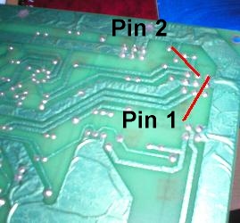
Soldering. The
first jumper wire i am going to add is from pin 6
to pin 3, if you look at the component
side of the AR pcb you will see that pins
1, 4, 7
are numbered on the pcb next to the connector showing that the pins
are numbered horizontally in three rows. Which means that the pins
(shown in pic 1 above) are pins 6
and 3. |
![]()
 |
 |
 |
|
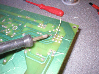
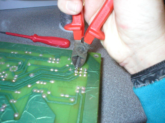
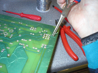
Soldering cont... Now
i needed to add a second jumper between pins 2
and 1 (shown in
pic 1above). Again i started
by adding just a little extra solder to the solder blobs on pin 2
and 1, then gripping the
wire in a pair of long nose pliers i laid the end of the wire against
pin 2 and heated the solder blob
with the soldering iron |
![]()
 |
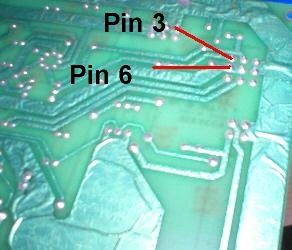
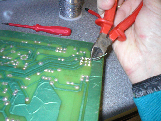
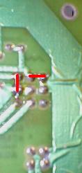
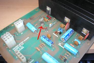
Checking your work. I
had now
made the "Sense Mods", by adding the jumper between pin
6 and pin 3
i have modded the positive + sense
circuit and by adding the jumper between pin 2
and pin 1 i have modded the negative
- sense circuit. All this left me
to do was make a good physical inspection of my work, to make sure
i was happy with my soldering and more importantly to make sure none
of the jumpers i had added were accidentally touching any other pins
they shouldnt. As pic on left is not too clear, pic on right shows jumpers highlighted in red. |
 |
![]()
|
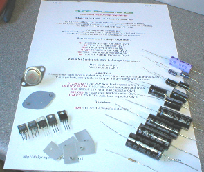
Rebuild Kit. With
the Sense Mods completed its now just a case of replacing the aging
parts on my AR pcb, that in some cases may have been on there since
1979 ! Rebuild kits are Available here. |
 |
![]()
|
|
Transistors.
|
![]()
|
Transistors cont...
|
|
![]()
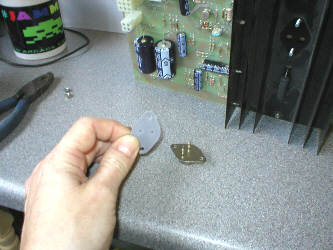 |
Insulating Mica's.
|
![]()
|
|
|
![]()
|
|
|
![]()
|
Amplifiers.
|
|
![]()
 |
The Infamous R29 Resistor !
|
![]()
 |
Adjustable Voltage Regulator.
|
![]()
|
Capacitors.
|
 |
![]()