
|
Pinx's
Atari
Asteroids Restoration...
|
![]()
 |
 |
 |
 |
 |
|
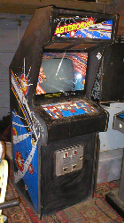
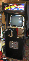
As
it came in.
|
Front
view.
|
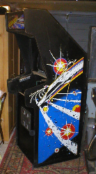
Left
side .
|
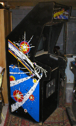
Right
side.
|
Start
to clean.
|
![]()
 |
 |
 |
|
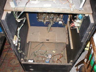
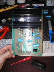
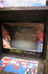
Inside.
|
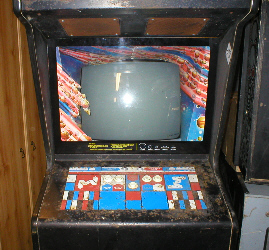
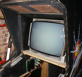
Monitor
(no screen burn).
|
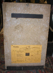
Back
door.
|
![]()
 |
Audio Reg (AR1). With this restoration, i decided to start here, mainly because this is my first vector cab and other than the power brick, it was the only thing in it that i had worked on before. |
![]()
|
Replacing components. So
i order'd a Bob Roberts
rebuild kit and replaced all the caps and the TIP32
transistor at Q2 and the
2N3055 in the black heatsink. |
 |
![]()
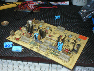 |
Deflection pcb. The
Deflection pcb was supplied as working, but as i want the game to
be reliable, i decided to re-cap it anyway, bearing in mind that this
game was made in 1979! it
pays to replace as many parts as you can obtain, rather than just
replace the parts that go, as you normally find that putting in a
new part, puts more of a strain on the old parts still being used. |
![]()
|
Replacing components. There
are 2 capacitors at locations C804 and
C806 they are 470uf
50V caps. Rather than shop around
for these caps i order'd a Electrohome GO5/801rebuild kit |
 |
![]()
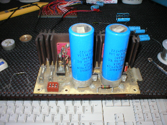 |
Monitor Regulator pcb. This pcb, has the job of smoothing out the voltages supplied to the monitor, hence the two large blue filter caps. Just in front of these but behind the large heatsinks are 2 small capacitors that are prone to failure. |
![]()
|
Monitor Regulator pcb cont... These small caps are located at C102 and C103 they are 1.0uf 50v capacitors and come supplied in the rebuild kit. When working on this pcb, you must pay very special attention not to accidentally short between the connections on the large blue caps at C100 and C101 as these store alot of residual current. YOU HAVE BEEN WARNED !! |
 |
![]()
|
|
|
|
Deflection Transistors Heatsink. These
are the main "X" & "Y" transistors, that give
the monitor its amplification. The "X" axis has a 2N3792
at Q707 and a 2N3716
at Q708. The "Y" axis has a
2N3792 at Q607
and a 2N3716 at Q608. |
![]()
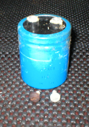 |
Big Blue. The
large blue capacitor in the middle of the power brick is a logic filter
capacitor and due to the age of this component, it is probably no
longer doing its job properly. It's job is to smooth out the 5+
volts, going to the logic pcb in the game. It is a 27000uf
16V capacitor. These can be obtained from Bob
Roberts in the U.S. |
![]()
 |
 |
|
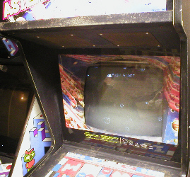
After
only 2 weeks of work its alive already !!
|
![]()
|
But then... After only a week of playing it decided to die... and all that could be seen on the screen was a thin horizontal line. This meant that somehow the monitor had lost its "Y" axis. So the first thing i did was meter the transistors in the "Y" section. The large ones on the big heatsink were o.k. but a TIS98 transistor on the Deflection pcb located at Q601 meter'd duff. |
|
![]()
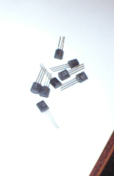 |
TIS98 transistors. Not exactly easy to source, as they are pretty much obsolete now, but after asking on the Vector mailing list and snooping around on the net, i managed to get some from Dial Electronics. So rather than just replace the one that had died, i shot gunned the whole deflection pcb and replaced them all... |
![]()
|
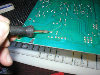
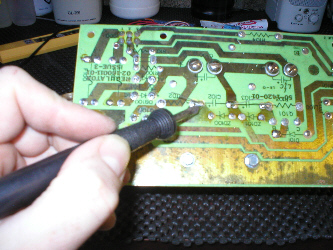
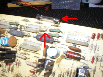
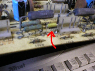
F600 axial lead fuse. After replacing all the TIS98's i put the deflection pcb back in the cab and tried it, but still just a flat line. Which had me really baffled, as i had replaced all the transisors in the "Y" section (and the "X" section too) and so i had to remove the deflection board again and start metering other components and found the 2 amp axial lead fuse at F600 was metering open. I had never seen one these before and didnt have any, so i solder'd a couple of legs cut off a spare capacitor onto the old one and then solder'd a 2A fast blow fuse across them (see arrows in pic) and this did the trick. |
 |
![]()
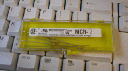 |
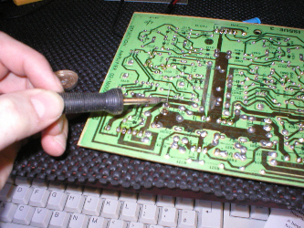
Axial lead fuses. When
looking at the schematics for the deflection pcb, it listed F600
as a fast blow 2 amp Pico fuse. |
![]()
|
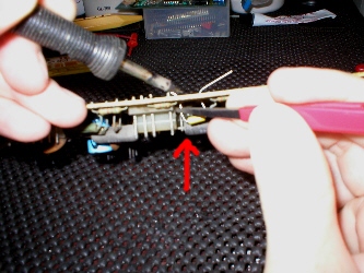
Axial lead (Pico) fuses cont... These
type of fuses have a very low tolerance for heat and so fitting them
is a bit of a delicate task. In order for me to solder it to the pcb
i used a heatshunt (in this case a pair insulated
tweezers) and left some length on the leads, so i could hold
it in place with |
 |
![]()
 |
Axial lead (Pico) fuses cont... Once it was safetly in place, i then checked it for continuity with a multimeter, to make sure it had'nt blown during soldering. It was then just a case of re-installing the pcb back in the cab. (pic shows new Pico fuse fitted, not a great photo but you get the idea) |
![]()
![]()
![]()