
|
Bally Space
Invaders Pinball
|

|
Restoration cont... All content on this site Copyright ©2002-2006 Dave Pinx. All rights reserved. |
![]()
 |
 |
![]()
|
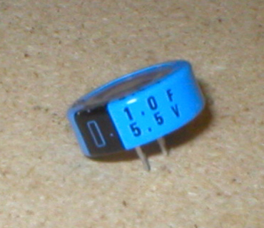
Memory
capacitor.
I bought a 1 Farad memory capacitor from Maplins, to replace the battery i removed, these as i mention'd before dont suffer from any leakage when they become old. As the pins on the capacitor are very close together, it will not fit into the origional holes for the battery, so i had to drill a hole just to right of the positive solder hole (see pic above right) Once i had the hole, i heated the solder in the positive hole and pushed the capacitor in, i then solder'd the back of the positive pin. The negative pin (nearest black band on cap) was then obviously in the hole i had drilled, which has no solder contact point, so i bent the leg outwards and solder'd a length of black wire to it. (see pic right) |
 |
![]()
 |
Memory
capacitor cont.. |
![]()
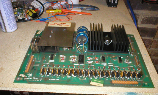 |
Solenoid
Driver pcb.
This pcb, tells all the solenoids (coils) on the playfield when to fire on and off and as with some of the other pcb's in the machine, this needs some modifications and upgrades. This pcb is also the one that holds the High Voltage section, making it dangerous to work on. WARNING, if you do not know what you are doing around high voltage pcb circuitry, do not attempt this, as there is a high risk of electrical shock from either of the two large blue capacitors ! |
![]()
|
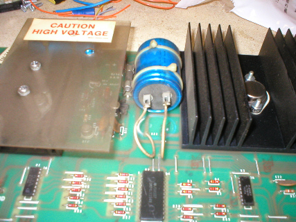
Solenoid
Driver pcb cont....
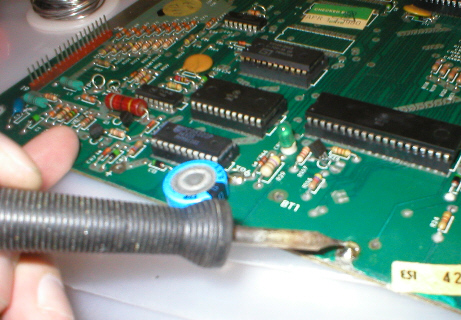
The large blue capacitor in the middle of the pcb is known as C23 it is a logic filter capacitor and due to the age of this component, it is probably no longer doing its job properly. It's job is to smooth out the 5+ volts, going to all the logic pcb's in the game. It is a 20 volt 11,000 mfd capacitor, but it is better to replace it with a larger one. |
 |
![]()
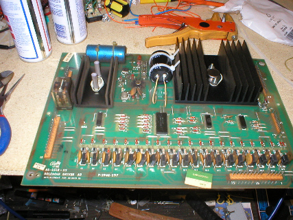 |
Replacing
C23 capacitor.
I managed to get a 25 volt 15,000 mfd capacitor, from RS, which was only a little smaller in physical size. I then unsolder'd both leads from the bottom of the old C23, making extra special care not to short between these two pins by accident (nice large pop if you do !) Once the wires were free from the pins, i then used side cutters to cut off the two cable ties holding the capacitor to the pcb itself. It was then a case of fitting two new cable ties through the holes and doing them up around the new C23 capacitor (this one was black in colour, see pic) This capacitor is polarised and therefor has to have its positive and negative sides connected up correctly! On the pcb by one of the wires to the capacitor there is marked a + for the positive connection, i twisted the capacitor around in the cable ties until the postive pin was in line with the positive wire. (the capacitor is marked for negative side only) It was then a simple case of soldering the correct wires to relative pins. |
![]()
|
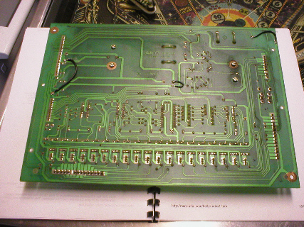
Solenoid
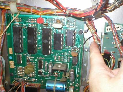
driver pcb, jumper wire mods. |
 |
![]()
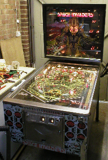 |
It's
Alive, YAY !!! |
 |
![]()
 |
 |
|
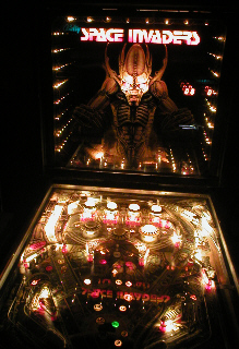
But
an hour later..... |
![]()
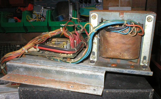 |
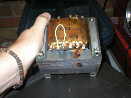
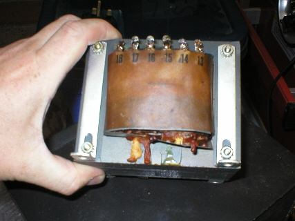
Used
replacement transformer. The transformer was rusty and looked very sorry for itself, i was not optomistic of it working at all, but as i had paid 20 quid for it plus the shipping, i had to give it a go. I unsolder'd all the wires off the transformer, which took some time as the solder was very old and didnt want to melt, so as a cheat i squirted liquid flux on the solder and then added new solder which helped the old stuff melt. I then bolted the transformer to the good power supply and solder'd all the wires on. |
![]()
|
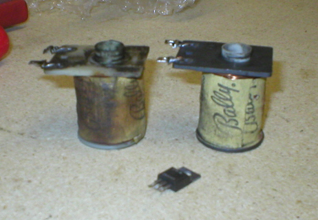
Locked
on coil. In pic, burnt coil on left, replacement on right and the duff transistor in front. |
 |
![]()
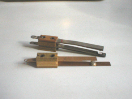 |
Flipper
leaf switches. Another little job done. |
![]()
|
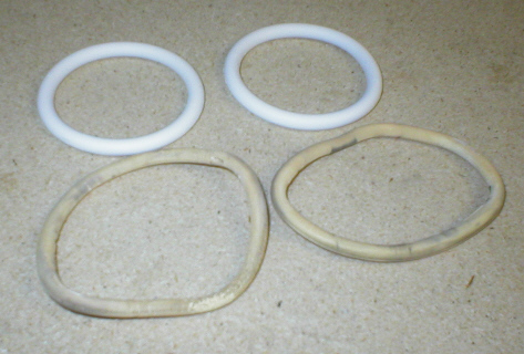
New
Rubbers. pic on right shows how the slingshot rubbers have stretched and aged in comparison to the new ones. |
 |
![]()
|
Alive
again. ! WARNING, the adjustment for this voltage is under a safety cover, as this area of the pcb is Dangerous to work on ! I am happy to say that it has been working fine for a week now and is getting alot of use (i cant get pinxy off it), as with the Pole Position project, this was a quick but rather intense project and with it being my first in pinball repair, i am very pleased with the outcome. |
 |
![]()
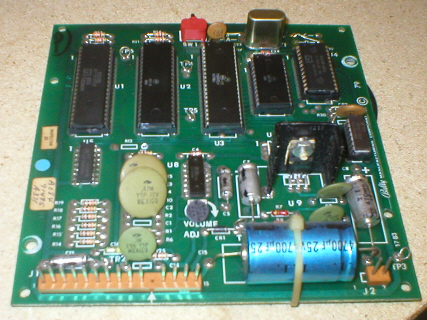 |
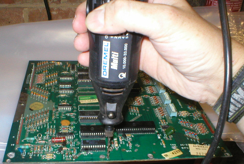
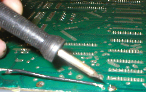
UPDATE...
This is the sound pcb, and as i mention'd earlier, i had a very slight hum sometimes, depending on how much load was on the game. I figured this to be a bad ground as the pcb does'nt ground itself against its mounting points, it only gets its ground from pins 6 and 14 on connector J1. TP3 (test point) is a ground point, so i added a length of black wire to the solder blob on the back of TP3 (see pic bottom left), i then mounted the pcb back in the backbox and measured the black wire off to the nearest mounting bolt hole. I then cut the wire to this length and crimped on an eyelet, it was then just a matter of putting the bolt through the eyelet crimp and bolting it to the pcb mounting point. (see pic bottom right) |
![]()
 |
 |
![]()
 |
As
with all my projects i like to thank any people who helped, For
help : Alan,
Willie, Malc, Joolz, |
Click here for Home.
![]()