How to convert
|
|
 |
|
to Jamma cont....
![]()
|
All content on this site Copyright
©2002-2006 Dave Pinx. All rights reserved.
|
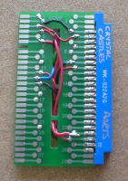 |
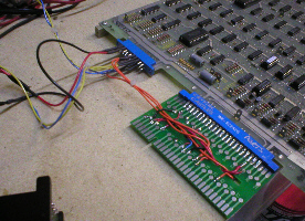
Adapter
after basic connections.
So, after making the basic connections, you should have an adapter that looks something like this. Pic on left is parts (comp) side and Pic on right is solder side. Now we have the controls and speaker connections to make, these will invovle the second small 2 x 10 way edge connector, the track ball and the amplifier for the sound. At this point, i get a paint pen and write on the edge con what game it is for and i also write parts on the part side and solder on the solder side. This way at a glance you know what its for and which way to put in on the pcb. |
 |
![]()
 |
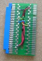
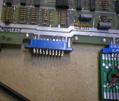
Small
edge connector.
The small edge connection on the Crystal Castles pcb is a 2 x 12 way, but these i could not find anywhere, so i got a 2 x 10 way one instead and modified it to fit, as luckily, we dont use all the pins on the small connector. I used a 1mm thick needle file and a disposable stanely knife, to create a slot in the end of the edge connector. I started by filing first (pic on left) untill i got down to a point where i would of started to rub against the pins inside. Once i got to this point i used the knife to cut little nicks out, untill i was flush with the bottom of the ledge (pic on right). |
 |
![]()
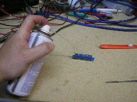 |
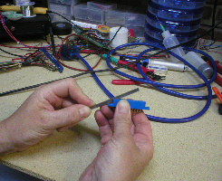
Small
edge connector cont...
Once i had done this i gave the whole connector a good blow out with an air duster (can of compressed air). Then i lined the edge connector up with pin N on the edge connection (1st pin on left, see pic on right) so that pin A and B hung out of the right hand end of the connector through the slot i had filed / cut earlier, it was then a matter of pushing it on, so that it sat in place. Now is a good time to get a paint pen and right part side on this con too. |
 |
![]()
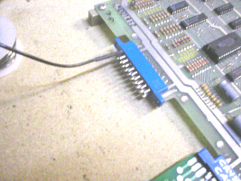 |
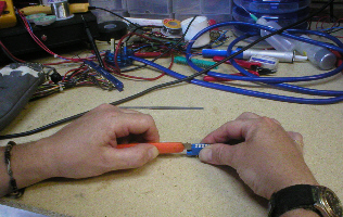
Small
edge connector wiring. |
 |
![]()
 |
|
![]()
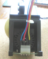 |
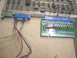
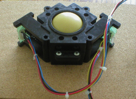
Optical
wheels and loom connectors. Now turning
the enclosure on its other side (so the left
encoding wheel is facing you) i again number these pins from
left to right :
1, 2, 3, 4 .
So this is the Left hand connector and the wiring for this is as follows
: |
 |
![]()

Click here for Home.
![]()